|
||
|
A Pitot tube is a measuring instrument used to measure fluid flow, and more specifically, used to determine airspeed on aircraft. The Pitot tube is named after its inventor, Henri Pitot, and was modified to its modern form by Henry Darcy.
Pitot tube
The basic instrument consists of two coaxial tubes: the interior tube is open to the flow (i.e. perpendicular), while the exterior tube is open at ninety degrees to the flow (i.e. parallel). A manometer can be used to measure the difference between these two pressures and using Bernoulli's equation the flow rate of the fluid can be calculated.
The exterior tube, with an opening parallel to the flow, will register the Static Pressure. The interior tube, with an opening perpendicular to the flow, will register the Stagnation Pressure. Stagnation pressure is made up of Static Pressure plus Dynamic Pressure (caused by the force of the fluid flowing into the tube interior). By measuring the pressure difference between the Static Pressure (exterior tube) and the Stagnation pressure (interior tube) allows the velocity of the fluid flow to be determined.
The Pitot tube has two tubes: 1. Static tube (b): The opening of the static tube is parallel to the direction of flow. It measures the static pressure, since there is no velocity component perpendicular to its opening. 2.
Impact tube (a):
The opening of the impact tube is perpendicular to the flow
direction. The point at the entrance of the impact tube is called as the
stagnation point .At this point the kinetic energy of the fluid is
converted to the potential energy. Thus, the impact tube measures the
total pressure (also referred to as stagnation pressure) i.e. both
static pressure and dynamic pressure (also referred to as impact
pressure). The two tubes are connected to the legs of a manometer or equivalent device for measuring pressure.
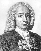
Henri Pitot (May 3, 1695 – December 27, 1771) was a French hydraulic engineer and the inventor of the Pitot tube, which measures flow velocity.
Beginning his career as a mathematician and astronomer, Pitot won election to the Academy of Sciences in 1724. He became interested in the problem of flow of water in rivers and canals and discovered that much contemporary theory was erroneous— for example, the idea that the velocity of flowing water increases with depth. He devised a tube, with an opening facing the flow, that provided a convenient and reasonably accurate measurement of flow velocity and that has found wide application ever since (e.g., in anemometers for measuring wind speed).
Appointed chief engineer for Languedoc, he performed a variety of maintenance and construction works on canals, bridges, and drainage projects. His major work was construction of an aqueduct for the city of Montpellier (1753 - 1786), including a stone-arch Roman-type section a kilometre (more than 1/2 mile) in length.
Bernoulli's equation
Bernoulli found that the Total Pressure was a constant. The total pressure is defined as the static pressure plus the kinetic, or dynamic, pressure. This is really just another statement of the conservation of energy. This principle forms the basis for a wing to develop lift and also is the basis for the operation of an airspeed indicator.
Bernoulli's Law - Diagram 1.
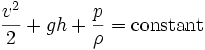
In fluid dynamics, Bernoulli's equation, derived by Daniel Bernoulli, describes the behavior of a fluid moving along a streamline. There are typically two different formulations of the equations; one applies to incompressible fluids and the other applies to compressible fluids. The original form, for incompressible flow in a uniform graviational field (such as on Earth), is:
These assumptions must be met for the equation to apply:
The decrease in pressure simultaneous with an increase in velocity, as predicted by the equation, is often called Bernoulli's principle. The equation is named for Daniel Bernoulli although it was first presented in the above form by Leonhard Euler.
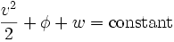
A second, more general form of Bernoulli's equation may be written for compressible fluids, in which case, following a streamline, we have: Here, φ is the gravitational potential energy per unit mass, which is just φ = gh in the case of a uniform gravitational field, and w is the fluid enthalpy per unit mass, which is also often written as h (which conflicts with our use of h in these notes for "height"). Note that
where ε is the fluid thermodynamic energy per unit mass.
The constant on the right hand side is often called the Bernoulli constant and denoted b. For steady inviscid adiabatic flow with no additional sources or sinks of energy, b is constant along any given streamline. Even more generally when b may vary along streamlines, it still proves a useful parameter, related to the "head" of the fluid.
Bernoulli's Law - Diagram 2.
Airfoils and Lift
An airfoil, the cross-sectional shape of an aircraft wing, owes its design to the work of Daniel Bernoulli, another physicist, who discovered and described certain principles of fluid flow. The "fluid", of course, is air, the medium through which aircraft move and depend upon for their lift. Mr. Bernoulli discovered some fairly simple relationships between fluid velocity and pressure which are the fundamental basis for the design of wings. Note that the discussion here really only applies to subsonic flow, not the compressible flow found in the transonic and supersonic cases. If you remember the picture of the pipe with a narrowed center section through which air is flowing from your high school or college physics class, you may also remember that as the air flows through the center narrow section, its velocity increases and its (static) pressure decreases. In diagram 1. above V2 > V1 and P1 > P2.
The airfoil is just an inside-out, asymmetrical version of the pipe used to demonstrate Bernoulli's Principle. The lift an airfoil generates is a reflection of the fact that the static pressure on the top surface of the wing is lower than that on the bottom surface. With a difference in static pressure, there is a net force in the direction of bottom to top. The dynamic pressure of a gas flow is q = 1/2 d V2, where d is the density and V is the velocity. The Total Pressure, Pt ,can thus be expressed as:
Bernoulli's Law - Wing section Diagram 3.
We can make some very broad simplifying assumptions and gain some insight into the operation of a wing, although even from the simple illustration above, it can be seen that the mathematics of the problem is already getting pretty messy. Let's just assume that the average flow velocity on the bottom surface of the wing is V1 and the average velocity on the top surface is V2. That being the case, using the second expression, above, the difference in static pressure across the wing would be:
Since Pt is a constant, the above expression reduces to:
Since pressure is a force per unit area, the total lift is directly proportional to the wing area and is directly proportional to the air density. Once again, skipping a lot of the math, an airfoil can be characterized by an artifice called its Coefficient of Lift or CL. The Coefficient of Lift is not a constant, but varies with the Angle of Attack. Once in possession of the Coefficient of Lift, however, we can state the total lift of a wing as:
DANIEL BERNOULLI
Daniel Bernoulli (Groningen, February 9, 1700 – Basel, March 17, 1782) was a Dutch-born mathematician who spent much of his life in Basel, Switzerland. He worked with Leonhard Euler on the equations bearing their names. Bernoulli's principle is of critical use in aerodynamics. It is applicable to steady, inviscid, incompressible flow, along a streamline. Born as the son of Johann Bernoulli,nephew of Jakob Bernoulli, younger brother of Nicolaus Bernoulli II,and older brother of Johann II, Daniel Bernoulli was by far the ablest of the younger Bernoullis. He is said to have had a bad relationship with his father. Upon both of them entering and trying for first place in a scientific contest at the University of Paris, Johann, unable to bear the "shame" of being compared to his offspring, banned Daniel from his house. Johann Bernoulli also tried to steal Daniel's book Hydrodynamica and rename it Hydraulica. Despite Daniel's attempts at reconciliation, his father carried the grudge until his death.
Daniel Bernoulli
When Daniel was five, his younger brother Johann Bernoulli II was born. He was a contemporary and intimate friend of Euler. He went to St. Petersburg in 1724 as professor of mathematics, but did not like it there, and a temporary illness in 1733 gave him an excuse for leaving. He returned to the University of Basel, where he successively held the chairs of medicine, metaphysics and natural philosophy until his death. His father wanted him to do this because he believed that there was no money in mathematics.
His earliest mathematical work was the Exercitationes (Mathematical Exercises), published in 1724, which contains a solution of the differential equation proposed by Jacopo Riccati (the Riccati equation). Two years later he pointed out for the first time the frequent desirability of resolving a compound motion into motions of translation and motions of rotation. His chief work is his Hydrodynamique (Hydrodynamica), published in 1738; it resembles Lagrange's Méchanique Analytique in being arranged so that all the results are consequences of a single principle, namely, in this case, the conservation of energy. This was followed by a memoir on the theory of the tides, to which, conjointly with the memoirs by Euler and Colin Maclaurin, a prize was awarded by the French Academy: these three memoirs contain all that was done on this subject between the publication of Isaac Newton's Principia and the investigations of Laplace. Bernoulli also wrote a large number of papers on various mechanical questions, especially on problems connected with vibrating strings, and the solutions given by Brook Taylor and by d'Alembert.
He is the earliest writer who attempted to formulate a kinetic theory of gases, and he applied the idea to explain the law associated with the names of Robert Boyle and Edme Mariotte.
Daniel Bernoulli also was the author in 1738 of the "Exposition of a New Theory on the Measurement of Risk", (Econometrica vol 22 (1954), pp23-36; Stanford Encyclopaedia of Philosophy) which St. Petersburg paradox was the base of the economic theory of risk aversion, risk premium and utility.
|
||
|
The
content of this website is copyright © and design copyright 1991 and
2013 Electrick Publications and NJK. All rights reserved. The bird |
||
|
BLUEPLANET BE3 | ELECTRIC CARS | ELECTRIC CYCLES | SOLAR CARS | SOLARNAVIGATOR |