|
||
|
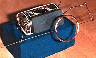
You can't get much simpler than the Beakman motor shown below. One battery, one magnet and one piece of wire formed into a coil which rotates in another piece of wire (a paper clip) held onto the battery at each end by a rubber band. It works, but apart from demonstrating the principle that electricity and magnets can be used to produce motion, it's not very practical.
Beakman - simple electric motor
Electric motors are everywhere! In your house, almost every mechanical movement that you see around you is caused by an AC or DC electric motor. By understanding how a motor works you can learn a lot about magnets, electromagnets and electricity in general. On this page we hope you will learn what makes an electric motor spin.
An electric motor is all about magnets and magnetism. A motor uses magnets to create motion. If you have ever played with magnets you know the law of magnets: Opposites poles attract and like poles repel. So if you have two bar magnets with their ends marked "north" and "south," then the north end of one magnet will attract the south end of the other. On the other hand, the north end of one magnet will repel the north end of the other. Inside an electric motor, these attracting and repelling forces create rotational motion.
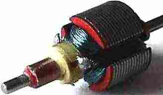
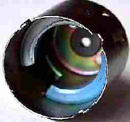
The armature (or rotor) is an electromagnet. Like the Beakman rotor above made of copper wound in a circle, the motor below has copper wound around a soft iron core. The field magnet is still a permanent magnet, only this time there are two semi-circular magnets fitted inside a steel casing. In some larger motors and generators the field magnet could also be an electromagnet.
In smaller motors it usually isn't to save the electricity that would otherwise be needed to make magnetism and also to reduce complexity. Actually, these days there are quite a few large motors using magnets to drive cars and the like. The Solar Navigator catamaran uses permanent magnet motors that are very efficient.
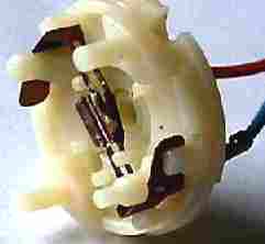
Armature Casing & field magnets Brush housing Motor assembly
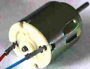
The motor we have dismantled above is a simple electric toy motor. Millions of these motors are made every year by Mabuchi and other famous producers. Mabuchi motors were used on the early 1/10th and 1/20th development models of Solar Navigator. If you take apart a small electric motor, you will find that it contains the same pieces described above: two small permanent magnets inside casing, two brushes held in a housing, and an electromagnet made by winding wire around pieces of shaped metal (laminations) on a steel shaft, known as an armature or rotor. Almost always the rotor will have three poles or more. There are two good reasons for a motor to have three poles or more:
It is possible to have any number of poles, depending on the size of the motor and the specific application it is being used in. Also, motors come in different shapes and sizes to fit almost anywhere. Special, very powerful (rare earth) permanent magnets can be used to boost power - although this increases the cost. Special brush materials can be used to improve power handling. And these days, instead of using a mechanical switch like the commutator, electronics can be used instead to get very accurate timing and sometimes exotic sine waves. This also eliminates sparking and brush wear problems, so reducing servicing.
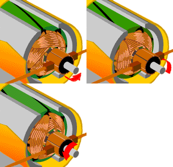
Motor turning
Other efficient dc designs do not have a conventional iron armature, but an ironless copper winding (a wire cylinder) set very close to a permanent magnet, such as in the Swiss Maxon design motors, used on Solar Navigator development models.
|
||
|
The
content of this website is copyright © and design copyright 1991 and
2006 Electrick Publications. All rights reserved. The bluebird logo |
