|
THE NATIONAL GRID
AUTOMOTIVE A TO Z CHARITY CLIMATE CHANGE CONTACT EVENTS HOME SITE INDEX
THE
NATIONAL GRID The
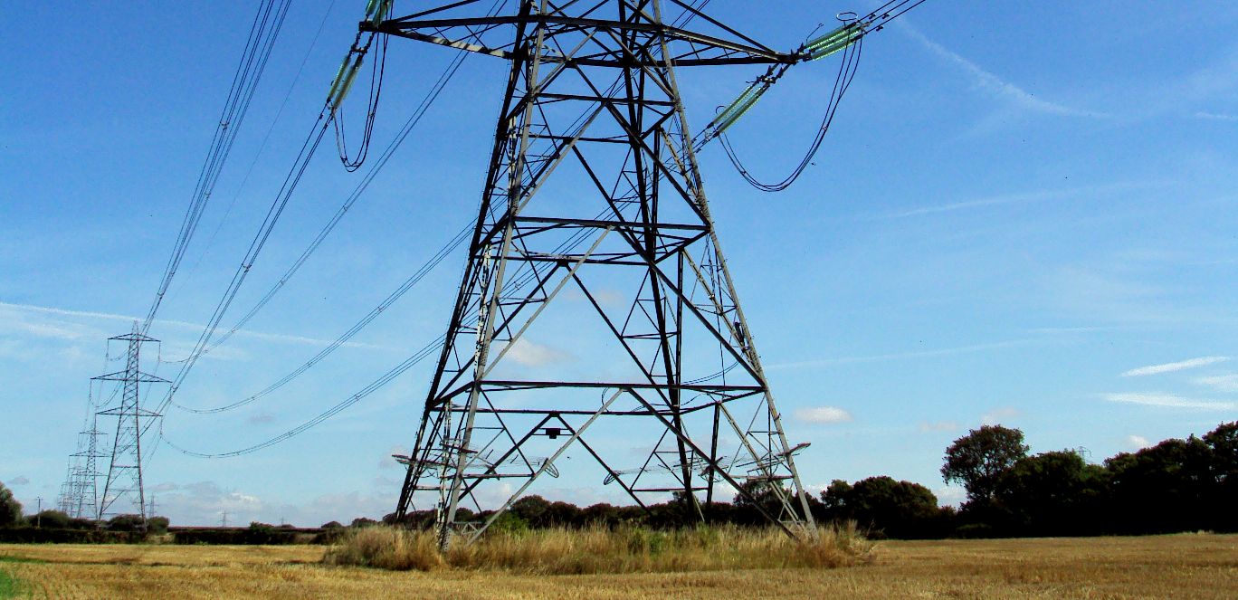
National Grid is the high-voltage electric power transmission network in
Great Britain, connecting power stations and major substations and
ensuring that electricity generated anywhere in England, Scotland and
Wales can be used to satisfy demand anywhere else in the country. In
Scotland the grid split into two separate entities, one for southern and
central Scotland and the other for northern Scotland, connected by
interconnectors to each other. The first is owned and maintained by SP
Energy Networks, a subsidiary of Scottish Power, and the other by SSE.
However, National Grid plc remains the System Operator for the whole UK
Grid. Mains
electricity comes in to our homes at a voltage of 230 Volts (V). However
it is not generated at 230 volts because the current in amps (A) needed to
push the energy through extremely large cables would be huge. Big currents
need thick cables that get hot. In our power stations electricity is
generated at 25,000 volts (at a current of 100,000 amps). Outside
power stations there are huge step-up transformers that take the voltage
from 25,000 volts to 275,000 volts (Kv). The voltage can be as high as
415,000 volts in the super grid. It
was Nikola Tesla who established the principles of three-phase
high-voltage electric power distribution while he was working for
Westinghouse in the United
States in the early 19th Century. TRANSFORMERS The
transformer is a vital part of the National Grid in terms of limiting
energy losses.
UK NETWORK SIZE - FROM 2005 SEVEN YEAR STATEMENT
Maximum
demand (2005/6): 63 GW (approx.) (81.39% of capacity)
LOSSES - FROM 2005 SEVEN YEAR STATEMENT
Joule
heating in cables: 857.8 MW
USEFUL FIGURES
Power = current (A) × Voltage (V) In Physics Code: P = IV
APPLICATION
VOLTAGES
SMART
SERVICE STATIONS
- This concept EV forecourt offers between 7.68 - 15.36MWh of solar
assisted energy storage with a capacity of between 48-96 battery
cartridges on a continuous charge cycle. Five of these stations (76.8MW)
could recharge (refuel) up to 10 trucks or cars a minute at peak times. During
rush hour, up to 300 vehicles might be serviced in one hour if drivers
don't dawdle, as in get out of their vehicles for any reason - there is no
need using automated billing - but this would require registered users.
The truck shown in these AutoCAD drawings is 3.55 wide x 3.5 high x 7.7M
long (8 x 11.5 x 25 feet). This station could accommodate trucks 4.46M
(14.77 feet) high as shown, or with a raised roof, almost any truck
currently on the market - though longer thinner trucks are more fuel
efficient. During
an eight hour day 2,400 trucks might be serviced using five forecourts on
the assumption that we start every morning with 96 x 5 = 480 slow charged
cartridges from off-peak supplies. The same forecourt might be used to
service fuel-cell
cars powered by stabilized hydrogen.
One size fits all. The secret is to KISS
the design (Keep It Simple Silly). There are only 28* moving parts in this
station, not including the gearbox for the solar powered drive motor. This
is possible because with this system the vehicles load the cartridges
themselves.
TOP ELECTRICITY POWER COMPANIES A - Z
According to Power-Technology.com, a website that provides market and customer insights in this sector, they listed these power companies (according to the 2018 Forbes calculation of net market capitalization, assets, sales and profit) as the biggest utilities:
KEPCO Korean Electric Power Corporation National Electric Grid & Central Electricity Authority (India) National Energy Board (Canada) National
Grid plc (formerly Central Electricity
Generating Board UK) State Grid Corporation of China TEPCO Tokyo Electric Power Company
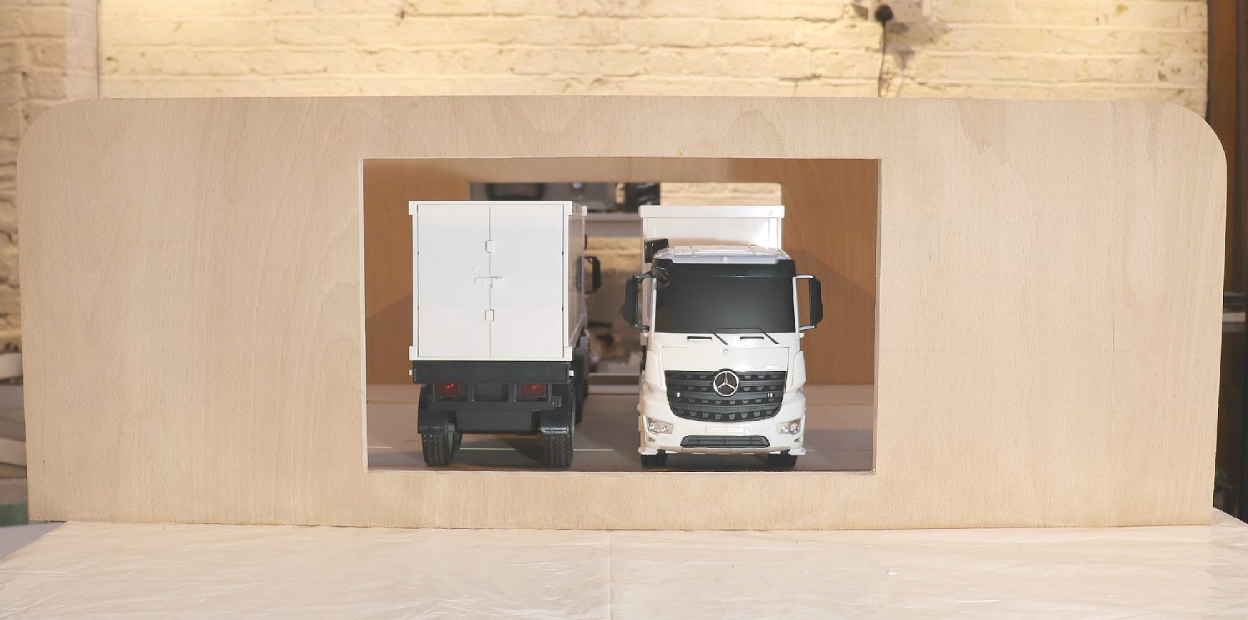
SMARTGRID - Service stations that use standard energy cartridges with (smart) compatibility built in for universal rapid charging of cars, buses and trucks - one size fits all.
1:20 SCALE MODEL - April 6 2020, a model of a service station that can refuel buses, truck and cars is under construction in workshops in Sussex, England. Seen here are two 1:20 scale Mercedes articulated container trucks inside. The makers are using plywood for the model of the building and some of the working parts - that cannot be shown due to patent law prohibiting prior publication. The Automated & Electric Vehicle Act 2018, makes it law in England that provision must be made for charging and refuelling of electric vehicles at service stops. This system would more accurately be described as a refuelling point - since the energy exchanges for trucks and cars are virtually instant. The full size building can be a quarter this size for city locations where space is limited. But for load levelling purposes, the larger the capacity of stored electricity, the more efficient the grid. Copyright photograph © 6 April 2020, Cleaner Ocean Foundation.
|